| |
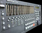
| FRONT
PANEL |
 |
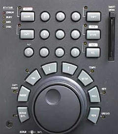 |
The
right side of the front panel features the numeric keys and the
buttons used to select the 99 location points and to set the values.
The Jog/Shuttle dial can also be used to edit the parameters by
pressing the dedicated function selector.
The Status LEDs indicate:
- an existing error condition and that the unit is performing a
complex operation and is momentarily busy;
- the MIDI and SCSI devices (HD or DVD) communication.
The files management keys and the two cursor keys (that select the
display menus or icrease/decrease the values) surround the dial.
The right side of this section features a Small Card slot. The Small
Card is used to update the the MX-2424 operative system.
|
|
|
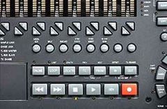 |
Above
the transport section there are the function keys that are used
to locate time positions, to assign the In and Out points, to set
the Loop mode and to enable the On Line mode.
On Line mode is useful to remotely control the MX-2424 from an external
unit in "Chase" or in a TL-Sync equipment chain.
The buttons located above the function keys give access to the editing
procedures.
|
|
|
| REAR
PANEL |
 |
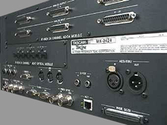 |
The
picture on the left shows the MX-2424 rear panel.
The upper part of the panel features a 24 In/Out analog interface
with 25-pin D-Sub connectors.
Below an optional ADAT digital card, featuring 6 Ligthpipe (optical)
connectors has been installed.
Analog and digital ports can be used simultaneously. 8 channels
groups can be alternatively selected.
|
|
|
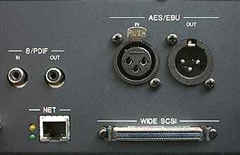 |
The
built-in digital ports include AES/EBU and S/PDIF 2 channel I/O.
The picture shows also a 68-pin Fast/Wide SCSI-2 port (80 Mb/sec),
for external storage devices connection (i.e.: HD).
On the left, a RJ-45 port is available for 100 Mb Ethernet connection
to a PC running the MX-View editing and control software.
A "crossing" type Ethernet communication cable must be
used when the MX-2424 is connected directly to the computer.
|
|
|
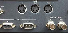 |
The
MIDI In connector allows to lock the MX-2424 to MTC (MIDI Time Code)
and MMC (MIDI Machine Control) codes for chase play and record.
MTC and MIDI Clock can also be internally generated and transmitted
thru the MIDI Out connector.
The BNC Video Sync In connector allows to lock the MX-2424 sample
clock to incoming Black Burst or Color Bars using PAL or NTSC video
signals.
These signals are then transmitted by the Video Thru connector,
that is self-terminating.
The TL-BUS allow communication and sample accurate synchronization
(transport and timing) of up to 32 units.
|
|
|
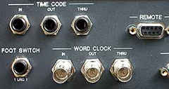 |
Through
the Time Code ports (balanced 1/4" TRS connectors) the MX-2424 can
receive and send the SMPTE Time Code, that can be used for Chasing
purposes and can also be generated.
The Thru connector sends out the Time Code coming in to the In port,
without any transmission delay. The Time Code can also be used as
a Timing source.
The Wordclock can be received and transmitted thru dedicated BNC
ports.
The Remote connector is used to connect the optional RC-2424 remote
control unit or other RS-422 standard controllers. Anyway,the MX-2424
can also be remotely controlled through an ADAT LRC (for basic transport
control) or a footswitch (for Record Punch In/Out) if they have
been connected to the Footswitch port.
|
|
|


